
Bridge Design
[Design Rationale]
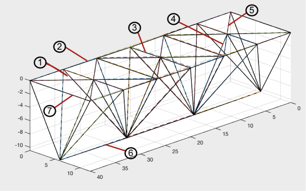
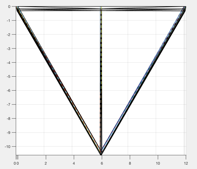
Our bridge can be divided into three triangular prisms of equal length (40/3 ft) and width (12 ft), making it 12 ft wide, 40 ft long, and 10.392 ft tall. Each prism consists of 7 tetrahedrons. The tetrahedron, according to the fundamentals of statics, is one of the strongest 3-D shapes, which is why we included multiple iterations thereof in our design. The four external joints we have included are to be attached to both ends of the ravine. Hence, the bridge will be entirely below the surface over which the trucks will pass. Since safety was not part of the design criteria, we chose not to expend any extra resources on side railings! Overall, we chose to focus more on lowering the cost of our bridge (less than $13 000!) rather than minimizing deflection. Nevertheless, our design still proves to be strong in that it resists normal stress very well. Our deflections values were 3.9457 in. in the z direction and .2797 in. in the y direction.
Bill of Materials
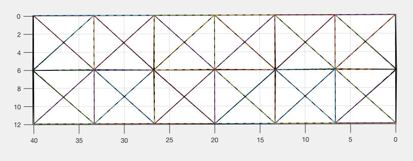
Top View
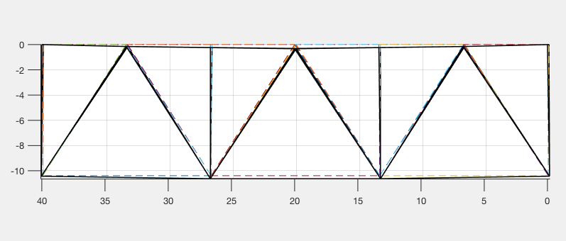
__________________________________Front View______________________________________R.H. Side View
[Loads and External Reactions]
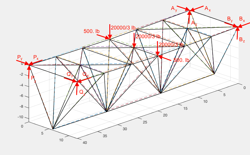
Load(s):
20.0 kips in the negative z direction — force from passing vehicles divided into three
500 lbs in the positive y direction — force from wind in that direction
500 lbs in the negative y direction — force from wind in that direction
External Reaction(s):
We included four external joints all stuck in the ground at points A, B, P, Q:
Ax= -4.96 kips, Ay= -4.69 kips, Az= 5.00 kips
Bx= -4.03 kips, By= 4.19 kips, Bz= 5.00 kips
Px= 4.96 kips, Py= -4.69 kips, Pz= 5.00 kips
Qx= 4.03 kips, Qy= 4.19 kips, Qz= 5.00 kips
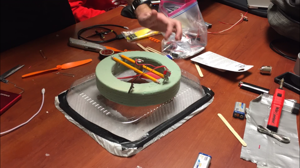
Hovercraft Design
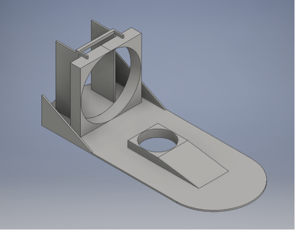
A design of our prototype created using Autodesk Inventor. Not included in the design graphic is a plastic bag that we intend on attaching to the entire base of the craft; this structure enabled lift by intensifying the action-reaction pair of forces.
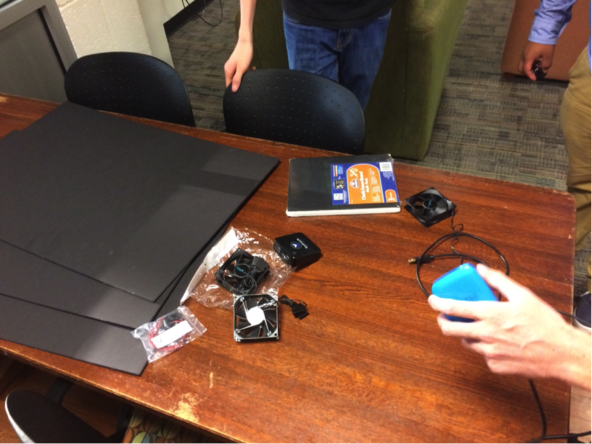
These are the materials that were used for the construction of our prototype and final design. The scale of the design enabled us to design two separate models for the purpose of testing without exceeding the monetary limit. In fact, the materials list as shown did not surpass $20.
[Design Rationale]
 Fans, due to the angled disposition of the blades thereof, generate considerable twisting or spiraling of the air stream generated thereby. Energy is wasted due to the fact that airflow is not directed straight to the rear of the machine but at an angle from the longitudinal axis.
Increasing air flow from a fan of a given diameter and rotational speed requires more fan blades and results in more twisting of the air stream and further inefficiencies. To conserve energy and rely on a limited, on-board emf source, we attempted to:
1. Control and optimize airflow within the craft;
2. Carefully account for the distribution of weight on board;
3. Construct two circuits independent of one another;
4. Reduce static and kinetic friction between surface and plastic bag;
5. Increase the rigidity and stability of the craft so that lift is made possible.
Boat Design
[Project Statement]
In engineering design we often what to maximize or minimize certain values to find the best possible design. For this project we would like to maximize the amount of weight that we can carry in a boat given a single sheet of poster board.
Temperature Measurements of a Thermal Plant
[Report]